Home   About Us   News   Contact Us
 

32/64/128/256/512/1024/2048/4096 Point FFT Core


General Description

  The FFT4096 core the FFT and IFFT computations for N input samples, where N can be any power of 2 between 32 and 4096 (32, 64, 128,...…4096), in hardware with very low latencies. The core also supports 2N-point real time samples to complex symmetric frequency samples FFT and N complex symmetric frequency samples to 2N time domain real samples IFFT.
 
Features


Supports 32/64/128/256/512/1024/2048/4096 point complex FFT and IFFT and up to 8192 point real-to-complex and complex-to-real FFT and IFFT and can switch dynamically. The real-to-complex and complex-to-real FFT/IFFT does not require any additional memory.

Built-in bit reversal. Outputs in natural order

Supports reading output data in any order (read address)

Low Latency. Can be customized to improve latency vs. gate count


Throughput of 1 sample per clock

Parameterized bit widths and fixed-point option.

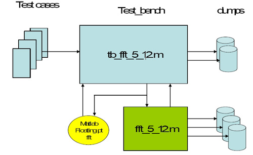
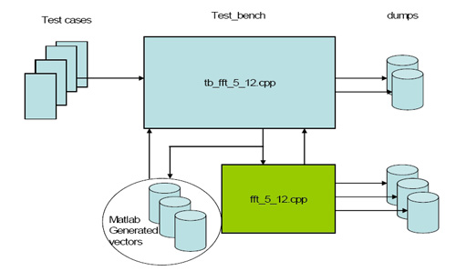
Test bench with fixed-point Matlab and optional C++ models

Available in ASIC and FPGA technologies

Minimal gate count implementation

Supports flushing and re-starting of the FFT operation instantly

Configurable bit width based on SQNR requirement for random inputs or for a specific stimuli pattern.

Customization for OFDM applications

 
Applications
 

DSL

Broadband over power lines
Digital Video Broadcasting (DVB)
Ethernet-over-coax
Other OFDM-based communications

 
CORE PINOUT

  CLK   1   In   System clock
  reset_n   1   In   Asynchronous reset
  Enable   1   In   Enable for the core
  Abort   1   In   1 pulse. Abort current operation
     and return to reset state
  fft_ifft_n   1   In   1: FFT mode
  0: IFFT mode
  fft_size   4   In   Number of carriers.
  0 – 4 : invalid
  5 : 32
  6 : 64
  7 : 128
  8 : 256
  9 : 512
  10 : 1024
  11 : 2048
  12 : 4096
  13 – 15 : invalid
  process_mode   1   In   0: complex to complex
  1: complex to real if IFFT
       real to complex if FFT
  Start   1   In   1 pulse. Start processing
  manual_shift_mode   1   In    0 : Auto scaling mode
   1 : Manual scaling mode
  scaling_shift_in   12   In   12 bit vector for manual scaling.
Each bit applies scaling at the corresponding radix-2 stage (consider radix-4 as 2 radix-2 stages for this purpose).
a. 0: no scaling
b. 1: scale by 2.
  Ready   1   Out   Asynchronous reset
  fft_stage   3   Out   Enable for the core
  Progress   13   Out   System clock
  sat_flag   1   Out   Asynchronous reset
  scaling_shift   5   Out   Enable for the core
       
  Memory Interface (4 points per address)
  mem_wr   1   Out   Write to buffer. 1 pulse.
  mem_wr_addr   10   Out   Buffer address for write
  mem_wr_data   128   Out   Data to write to buffer
  mem_en   1   Out   Read from buffer. 1 pulse
  mem_rd_addr   10   Out   Buffer address for read
  mem_rd_data   128   In   Data read from buffer. The
        latency of the data (X) can be
        more than 1 clock.
 
MATLAB MODEL
   

Serves as the gold reference

Used as a platform by customers to optimize the parameters and sign-off on performance.
RTL and C++ outputs will match bit-to-bit with Matlab.

 
C++ Model

C++ model environment is very similar to Matlab:

C-Model Environment

 
  4096   6250   7274
  2048   3278   3690
  1024   1370   1626
  512   730   858
  256   330   394
  128   202   234
  64   58   74
  32   34   42
 
Deliverables
 
Synthesizable Verilog RTL source code
Fixed-point Matlab model
Optional C++ bit accurate model
Simulation scripts
Self-checking Test environment
 
  Test-bench
  Test-vectors
  Expected results
Synthesis scripts
User Documentation