Home   About Us   News   Contact Us
 

FFT1-32-512/4 Core 32-512 Point Streaming FFT Core


Introduction

The FFT1-32-512/4 core implements 32, 64, 128, 256, and 512 point FFT and IFFT in hardware that runs at the clock frequency four times higher than the input sampling frequency.
Symbol

Key Features

Supports 32/64/128/256/512-point complex FFT and IFFT and can switch dynamically
Inputs and outputs data in the natural order
Throughput of 1 sample (In-phase I + quadrature Q) per 4 clocks; no-gap processing of the input data
Parameterized bit width.
Test bench and bit-accurate model
Available in ASIC and FPGA technologies
Minimal gate count implementation
Programmable inter-stage scaling register
Applications
Communication System
Signal Analysis
Pin Description
CLK Input   Core clock signal
Cen Input   Synchronous enable signal. When LOW the core ignores all its inputs and all its outputs must be ignored.
MODE[3:0] Input   Mode
  • 0000 – complex-to-complex 32-bit FFT
  • 0001 – complex-to-complex 64-bit FFT
  • 0010 – complex-to-complex 128-bit FFT
  • 0011 – complex-to-complex 256-bit FFT
  • 0100 – complex-to-complex 512-bit FFT
  • 1000 – complex-to-complex 32-bit IFFT
  • 1001 – complex-to-complex 64-bit IFFT
  • 1010 – complex-to-complex 128-bit IFFT
  • 1011 – complex-to-complex 256-bit IFFT
  • 1100 – complex-to-complex 512-bit IFFT
START Input   HIGH  starting input data processing
READ Output   Read request on the input interface
WRITE Output   Write enable for the output interface
DI[ ],DQ[] Input   Input In-phase and Quadrature Data
QI[ ],QQ[] Output   Output In-phase and Quadrature Data
SCALE[8:0] Input   Manual scaling selection (when block floating point option is not enabled)
 
Memory Interface

The core requires four “duplex” memories (dual-port memories with one write and one read port). The depth of each memory is ½ of the maximum data block (256) and the width is one sample (for example, with 24-bit I and Q, each memory will be 256x48 bits).

 
Function Description

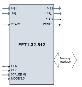
FFT1-32-512/4 can process single stream of 32/64/128/256/512 point FFT/IFFT with input and output data in natural order.

The FFT or IFFT radix operations start when START input is sampled high. The core will start reading the input data, asserting the READ signal each time it reads the data. The FFT data output will be streamed out after fixed latency. The core will indicate data output by asserting the WRITE output.

Core will continue to operate on incoming data stream block of 32/64/128/256/512 samples each while the START signal is high.

SCALE input allows setting of the inter-stage scaling for each of the 9 radix-2 FFT stages. A bit value of 1 in position N indicates that the input data of the stage N are scaled by a factor of 2.

 
Deliverables

Synthesizable Verilog RTL source code
Bit-accurate software model
Simulation scripts
Self-checking environment
Test-bench
Test-vectors
Expected Results
User Manual